Profinet Siemens
With the help of the following information you can integrate one or more HERMA 500 IE applicators into a higher-level controller – in this case Siemens Profinet S7-1500.
The steps required in the relevant development environment and the initialization (initial configuration) of the underlying parameters in the HERMA 500 IE are described.
You can find all information, sample projects and videos to download here
You can get more detailed information from the above download, incl. FAQs.
Prerequisites
- The Siemens TIA portal.
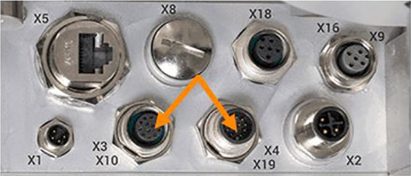
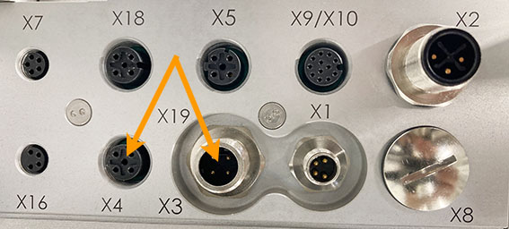
- Connection of the HERMA 500 IE to the customer’s controller.
- Optional connection of further applicators HERMA 500 IE
V1 (until end of 2021)
V2 (Facelift) as of 2022
Sample project
To test the successful integration, we provide you with sample projects that let you learn step by step how to switch on the HERMA 500 IE, dispense labels with it and change parameters, for example.
Sample project and associated video tutorial are also included in the download above
You can find a video tutorial here
Integrating the applicator into the PLC
TIA-Portal
The following must be reserved for each HERMA 500 IE:
- 8 bytes in the PA range
- 8 bytes in the PE range
- One data block per HERMA 500 IE applicator.
The function supplied in the sample project (usually FC8) controls the data traffic between the PLC and HERMA 500 IE. It can be used for all the connected HERMA 500 IE applicators and must be called separately for each data block. A separate data block is required for each HERMA 500 IE. The data blocks are identical.
The function and data block are protected. For the data block, this protection refers only to the fact that changes cannot be made unintentionally.
Preparations
The following settings must me configured prior to the first connection to the PLC:
- Under “Advanced settings --> Fieldbus settings --> Fieldbus selection (parameter 650)”, you must set “Profinet”.
- You cannot activate the fieldbus communication with the PLC (parameter 651) until parameter 650 is set to “Profinet”.
To access this parameter, you must be logged in as an administrator.
To apply the data and start in the new mode, you must briefly disconnect the HERMA 500 IE from the power supply (switch the HERMA 500 IE off and on again).
Adding functions and data blocks to your project
Before you begin, note that you must repeat the following steps based on the number of HERMA 500 IE applicators in your system. If you are only using one HERMA 500 IE, you only have to copy the networks, functions, data blocks and variables for “E1” (applicator 1). Repeat the steps for E2, E3 to En, if you are using more than one HERMA 500 IE applicator in your device.
- Open your actual project in the TIA portal.
- Open a second instance of the TIA portal and open the sample project provided by HERMA.
- Copy the relevant networks from the sample project OB1 block to your actual project in OB1. Repeat the process with the networks from the OB100 block.
- Copy the function “Init_H500_E1” from the sample project to your project. Repeat the process with the data block DB1 “Par_H500_E1”.
- Copy the function H500_Communication.
- Copy all the relevant PLC variables from the sample project to your project.
- In addition, copy the “Watch” and “Force” tables.
Following these steps, you can continue with the hardware configuration for the fieldbus.
Sample setup for configuration (S7-1500)
Firstly, you import the current GSD file for the network controller fieldbus to the project (this can be acquired from HERMA with the sample project). To install the GSD file, go to the main menu in the project view and choose “Extras --> Manage device description files (GSD)”.
Based on the number of HERMA 500 IE devices integrated in the project, the same number of fieldbus controllers should be added to the project. To do so, proceed as follows: Project view --> Devices & networks --> Network view --> Hardware catalogue --> Other field devices --> I/O --> HERMA GmbH. Select the latest version of the model (e.g. H500 PROFINET v4.4.0x). You can drag the device to the configuration using drag and drop.
You must now drag the Profinet configuration. The “Network” function must be activated to do so. You can then connect the PLC connection directly to the fieldbus controller connection (click and drag).
You must now parameterise the inputs and outputs of the fieldbus controller. The device overview opens automatically when you double-click the NETX from the network view. You may have to enlarge the window by dragging it. You can now change the addresses to the desired area (272 here) directly from the device overview. If you are using more than one HERMA 500 IE device, repeat this step accordingly. For example, use the address 280 for applicator 2, the address 288 for applicator 3, and so on. These addresses are dependent on their related peripheral input area. Simply double-click and change the relevant field. After you change the I/O addresses, you can click “Properties”, go to “General” and change the name to the corresponding applicator number (e.g. “E1”).
To ensure that the communication is working, you must adapt the IP address of the PLC and fieldbus controller. To do so, right-click them and choose “Properties”. Under “Properties -> PROFINET interface -> IP protocol”, enter an IP address that is suitable for communication with the PLC. For example, if the IP address of the PLC is: 10.120.0.1, then
- applicator 1 should have IP: 10.120.0.2, for example
- applicator 2 should have IP: 10.120.0.3, for example
- … and so on
Additionally make sure that the "Send clock" under "Properties / PROFINET interface / Real-time settings" is set to 1 ms.
Also set the PROFINET update time. With one to two applicators in the machine, the update time should be set to 2 ms. With three to four applicators in the machine, the update time should be set to 4 ms.
In the main cycle (OB1), the FC for controlling the communication for each HERMA 500 IE must be called once with the appropriate parameters (the corresponding peripheral input area and data block). Adapt these values if necessary.
Translate the hardware and software changes and load them to the CPU. You can now go online and test the availability of the participants.
The HERMA 500 IE is not available immediately because the same name and IP address as those in the hardware configuration must be assigned. To do so, go to “Online access --> Enhance your network adapter” and search for the HERMA 500 IE.
Adapt the name and IP address of the HERMA 500 IE in your project so that they match the hardware configuration. For example, use “E1” as the name for the first HERMA 500 IE and the following IP: 10.120.0.2
Once you have successfully completed the hardware configuration, the Profinet connection should function. The initialization parameters (Area BasicInit in the Data Block) should be set at a suitable point in the programme. There is an initialization function for each HERMA 500 IE (e.g. “Init_H500_ET1”). This function is only called once in the OB100 if the HERMA 500 IE is restarted or power cycling is performed.
You must also determine which parameters of the respective application must be transferred to the HERMA 500 IE in any event (Area Parameters.InitFlags) when the system is restarted.
In the main cycle (OB1), the FC for controlling the communication for each HERMA 500 IE must be called once with the appropriate parameters (the corresponding peripheral input area and data block).
All the remaining settings are transferred from the current initialization data content from the corresponding data block.
If you want to ensure that the initialization and/or configuration of the HERMA 500 IE is always the same, you must set all the parameters for the application to the correct values here.