OPC UA
The OPC UA server is generally integrated in every HERMA 500 applicator, but must be activated in order to use it.
For subsequent activation, please contact our customer service. Or via E-Mail under service-machines(at)herma.com
You can view options already activated in your HERMA 500 in its "Imprint" menu.
Prerequsites
- The OPC UA-server is activated for your HERMA 500
- The OPC UA-server is activated via parameter 620 in the „Extended settings“ menu.
- The OPC UA-server is specified via parameter 621 in the „Extended settings“ menu.
- The IP address is specified via parameter 610 in the „Extended settings“ menu.
- The HERMA 500 is connected via Ethernet at X5 with a RJ45 connector.
For parameter settings, you must be logged in with operator level 4 (default setting „4444“)
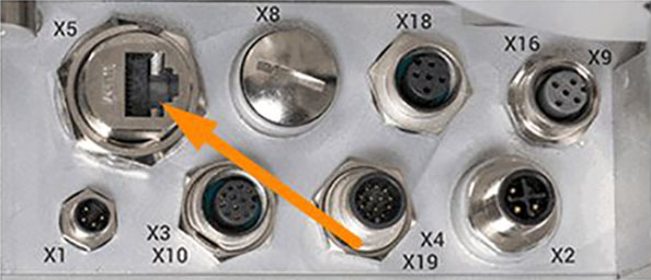
V1 (until end of 2021)
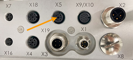
V2 (Facelift) as of 2022
Default settings
OPC UA-Port: 16664
IP-adress: 192.168.3.11
Opc.tcp://192.168.3.11:16664
Note on performance and operation on the display:
The internal system load in the HERMA 500 and thus the dynamics or the reaction speed on the internal display depend on the number of subscribed objects and the respective sampling interval. If more than 10 parameters are to be monitored, it is recommended to subscribe to the complete parameter array and to perform the individual parameter evaluation on the control side. For the sampling rate, 50 ms is theoretically possible. Practically this is not necessary and a rate of about 1 second is recommended. This means that the reaction times on the display are hardly noticeably delayed and operation is possible as usual.
Data structure
Objects
Server
-
Parameters
- Single
- Individual listing of all parameters. Parameters can be subscribed to individually. If several parameters are to be subscribed to cyclically or on change, it is recommended to access the arrays.
- Array
- Parameterarray: Array with all parameter values one after the other.
- MetaData:
- Numbers: Array with all parameter numbers in a row.
- Names: Array with all parameter names in a row. Names according to the set display language.
- BaseUnits: Array with units of the parameter values.
- MinValues: Array with the minimum permitted input values.
- MaxValues: Array with the maximum permitted input values.
- DecimalPositions: Array with the respective decimal places of the parameter values.
- MinAuthorizations
- IsReadOnlys: Array with marking of all read-only parameters.
- Single
-
Status Data
- ByType
- StatusType 0
- StatusType 1
- StatusType 2
- StatusType 3
- StatusType 4
- StatusType 5
- StatusType 6
- StatusType 7
- StatusType 8
- StatusType 9
- …
- StatusType 31
Status DataV2 (as StatusData, but without empty fields)
- ByType
-
Alarm
- ID: Current number of the message. The client can initiate the acknowledgement process by writing a zero.
- Severity: Distinction between alarm message (red) and event message (yellow).
- Message: Text of the respective message in the set national language.
- Desciption: More detailed description of the message in the set national language.
- Solution: If applicable, suggested solution in the set national language.
Types
Views
Parameters
As can be seen from the objects, the parameters are provided individually or as an array. The parameter array contains the pure numerical values of the individual parameters. In addition, there are separate arrays with, for example, the name, the decimal point, the physical unit, etc. The respective assignment can then be made via the position in the array. Parameters and parameter numbers are equivalent to those in the HMI of the HERMA 500.
Status data
Changes as of firmware version 22.09.26:
- New object "StatusDataV2": The length of the status arrays is limited. Superfluous blocks filled with zeros have been truncated. This saves data overhead during transmission and allows faster processing on the server and client sides.
- Status type 31 contains a selection of the data from status types 3 and 4.
The status data are partly writable and partly read-only. They represent all data that is not available via parameters. The breakdown of the status data is shown below:
StatusType0: Switch applicator from standby to automatic mode
Bit 0 = 0 -> Standby;
Bit 0 = 1 -> Automatic
StatusType1: Bit 0 = 1 -> Manual label feed; Prerequisite: Parameter 759 (Extended settings -> Access -> Dispensing access) is set to 1 (PLC + external HMI).
StatusType3: Data dependent on the labelling cycle.
-
StatusType3 Data dependent on the labelling cycle
uint32 Array Block number
uint32 or Bit
Designation
Description
0
uint32
Istweg1
Total distance of 1st labelling process in xx.x mm
1
uint32
Istweg1_2
Total distance of 2nd labelling process in xx.x mm with double label
2
uint32
Istzeit1
Time in msec for 1st labelling
3
uint32
Istweg1_2
Time in msec for 2nd labelling
4
uint32
wDurchm_rolle
Diameter determined of unwinder roll in mm
5
uint32
wDurchm_rolle_Aufw
Diameter determined of rewinder roll in mm
6
uint32
Zyclus_gesamt
Time for a total cycle
7
uint32
stSchlupf_Abmittel
Difference reference value to actual value with label synchronisation
8
uint32
stEt1_lang_Mittel
Mean value of path length on label mm
9
uint32
stSt1_lang_Mittel
Mean value of path length in gap
10
uint32
stEt2_lang_Mittel
Mean value of path length on label
11
uint32
stSt2_lang_Mittel
Mean value of path length in gap mm
12
uint32
stZeit_bis_Stop
Path length label until stopping mm
13
uint32
stWeg_Et_b_Stop
Time label until stopping mS
14
uint32
Virtgesch_z
Start speed with using a master encoder m/min
15
uint32
fd_Zaehler_Register
Count register
16
uint32
Gsumme_Et1
Number of total labelling cycles
17
uint32
Gstrecke_Et1
Total distance in meters
18
uint32
I_Zyklus
Load over cycle
19
uint32
U_ZK
Current voltage intermediate circuit in V
20
uint32
I_Etikett
Load over label
21
uint32
Abw_Leist_Mittel
Mean output of unwinder
22
uint32
Schlaufi_Leist_Mittel
Mean output of loop unit
23
uint32
Aufwickler_Leist_Mittel
Mean output of rewinder
-
StatusType4 Digital Status
uint32 Array Block number
uint32 or Bit
Designation
Description
0
Bit 0
Sigital_Status
Operation on (drive in control)
0
Bit 1
Sigital_Status
Automatic mode
0
Bit 2
Sigital_Status
Manual label feed possible
0
Bit 3
Sigital_Status
Error
0
Bit 4
Sigital_Status
Serious error
0
Bit 5
Sigital_Status
Ready
0
Bit 6
Sigital_Status
Labelling process active (feeding)
0
Bit 7
Sigital_Status
IE chip addressable
0
Bit 8
Sigital_Status
CAN unwinder present
0
Bit 9
Sigital_Status
CAN unwinder ready
0
Bit 10
Sigital_Status
CAN rewinder present
0
Bit 11
Sigital_Status
CAN rewinder ready
0
Bit 12
Sigital_Status
CAN loop unit present
0
Bit 13
Sigital_Status
CAN loop unit ready
0
Bit 14
Sigital_Status
CAN loop filler present
0
Bit 15
Sigital_Status
CAN loop filler ready
-
StatusType4 Digital: No_Ready_Why
uint32 Array Block number
uint32 or Bit
Designation
Description
1
Bit 0
No_Ready_Why
Applicator not active
1
Bit 1
No_Ready_Why
CAN module no response
1
Bit 2
No_Ready_Why
Transfer state – remove Ready signal
1
Bit 3
No_Ready_Why
Reserved
1
Bit 4
No_Ready_Why
Unwinder not ready
1
Bit 5
No_Ready_Why
Rewinder not ready
1
Bit 6
No_Ready_Why
Loop unit not ready
1
Bit 7
No_Ready_Why
Reserved
1
Bit 8
No_Ready_Why
Initialisation with control not yet completed
1
Bit 9
No_Ready_Why
Ready not present
-
StatusType4: Outputs Digital_Out
uint32 Array Block number
uint32 or Bit
Designation
Description
4
Bit 0
Digital_Out IO
Not used
4
Bit 1
Digital_Out IO
X19.3-EncA
4
Bit 2
Digital_Out IO
X10.8-Printer on
4
Bit 3
Digital_Out IO
X10.5-Dimout
4
Bit 4
Digital_Out IO
X10.4-Endout
4
Bit 5
Digital_Out IO
Not used
4
Bit 6
Digital_Out IO
X10.8-Print
4
Bit 7
Digital_Out IO
No_Feed
4
Bit 8
Digital_Out IO
X10.3-Ready
4
Bit 9
Digital_Out IO
Manual label feed in progress
4
Bit 10
Digital_Out IO
X19.12-Manual feed button
4
Bit 11
Digital_Out IO
X19.8-ACK
4
Bit 12
Digital_Out IO
X15.2-Teach
4
Bit 13
Digital_Out IO
X6.2-Transfer
4
Bit 14
Digital_Out IO
X19.10-No_Label
4
Bit 15
Digital_Out IO
X10.7-Fault
-
StatusType4: Inputs Digital_In
uint32 Array Block number
uint32 or Bit
Designation
Description
5
Bit 0
Digital_In IO
X7.5 PrinterBusy
5
Bit 1
Digital_In IO
X7.4 Printer Error
5
Bit 2
Digital_In IO
X6.4 Sensor
5
Bit 3
Digital_In IO
Reserved
5
Bit 4
Digital_In IO
X10.12-ACK
5
Bit 5
Digital_In IO
X55.4 Input rewinder
5
Bit 6
Digital_In IO
X19.7
5
Bit 7
Digital_In IO
Not used
5
Bit 8
Digital_In IO
X53.2 Input unwinder DIM
5
Bit 9
Digital_In IO
X52.2 Input unwinder END
5
Bit 10
Digital_In IO
X10.6 On/Off
5
Bit 11
Digital_In IO
X19.4 Manual feed button
5
Bit 12
Digital_In IO
X19.9 Lock
5
Bit 13
Digital_In IO
Not used
5
Bit 14
Digital_In IO
X15.4-Stop sensor
5
Bit 15
Digital_In IO
X16.3-Start sensor
-
StatusType4 General
uint32 Array Block number
uint32 or Bit
Designation
Description
2
uint32
w_DriveTemp1
Temperature inside housing
3
uint32
w_DriveTemp2
Temperature IPM
6
uint32
Gsumme_Einschalt
Power-on time applicator in sec
7
uint32
Gsumme_Betrieb
Operating time applicator in sec (active control)
8
uint32
Abwick_Betriebsstunden
Operating time unwinder
9
uint32
Schlaufi_Betriebsstunden
Operating time loop unit
10
uint32
Aufw_Betriebsstunden
Operating time rewinder
-
StatusType14 Firmware/Bootloader
uint32 Array Block number
uint32 or Bit
Designation
Description
0
uint32
DSP1_FW
Firmware DSP Core 1
1
uint32
DSP2_FW
Firmware DSP Core 2
2
uint32
DSP1_BL
Bootloader DSP Core 1
3
uint32
DSP2_BL
Bootloader DSP Core 2
4
uint32
Rangierplatine_FW
Firmware distributing board
5
uint32
Rangierplatine_BL
Bootloader distributing board
6
uint32
Abwickler_FW
Firmware unwinder
7
uint32
Abwickler_BL
Bootloader unwinder
8
uint32
Schlaufi_FW
Firmware loop unit
9
uint32
Schlaufi_BL
Bootloader loop unit
10
uint32
Aufwickler_FW
Firmware rewinder
11
uint32
Aufwickler_BL
Bootloader rewinder
12
uint32
Feldbus_BL
Bootloader field bus
13
uint32
Feldbus_FW1
Firmware 1 field bus
14
uint32
Feldbus_FW2
Firmware 2 field bus
15
uint32
Reserve
16
uint32
GeräteID
Unique Number of DSP
-
StatusType31 Special data selection from other status types
uint32 Array Block number
uint32 or Bit
Designation
Description
0
see StatusTyp3-15
Count register
1
see StatusTyp3-16
Total labelling cycles
2
see StatusTyp4-0
Digital Status (resolution in bit)
3
see StatusTyp4-1
No-Ready-Why (resolution in bit)
4
see StatusTyp4-4
Digital outputs (resolution in bit)
5
see StatusTyp4-5
Digital inputs (resolution in bit)
6
see StatusTyp4-6
Power-on time
7
see StatusTyp4-7
Operating time